SPDX-License-Identifier: Apache-2.0
Copyright (c) 2020 Intel Corporation
Converged Edge Reference Architecture for SD-WAN (Intel® Smart Edge Open uCPE Experience Kit)
- Introduction
- Universal Customer Premises Equipment (u-CPE)
- Software-Defined Wide Area Network (SD-WAN)
- SD-WAN Implementation
- CNF Configuration via OpenWRT Packages
- SD-WAN CNF Packet Flow
- Intel® Smart Edge Open Integration
- Deployment
- Resource Consumption
- References
- Acronyms
- Terminology
Introduction
With the growth of global organizations, there is an increased need to connect branch offices distributed across the world. As enterprise applications move from corporate data centers to the cloud or the on-premise edge, their branches require secure and reliable, low latency, and affordable connectivity. One way to achieve this is to deploy a wide area network (WAN) over the public Internet, and create secure links to the branches where applications are running. The primary role of a traditional WAN is to connect clients to applications hosted anywhere on the Internet. The applications are accessed via public TCP/IP addresses, supported by routing tables on enterprise routers. Branches were also connected to their headquarter data centers via a combination of configurable routers and leased connections. This made WAN connectivty complex and expensive to manage. Additionally, with the move of applications to the cloud and edge, where applications are hosted in private networks without public addresses, accessing these applications requires even more complex rules and policies.
Software-defined WAN (SD-WAN) introduces a new way to operate a WAN. First of all, because it is defined by software, its management can be decoupled from the underlying networking hardware (e.g., routers) and managed in a centralized manner, making it more scalable. Secondly, SD-WAN network functions can now be hosted on Universal Customer Premises Equipment (uCPE), which also host software versions of traditional customer premises equipment. Finally, an SD-WAN can be complemented by edge computing solutions, allowing, for example, latency-sensitive traffic to be steered to edge nodes for local processing, and to allow uCPE functions to be hosted in edge nodes.
This paper describes how the Open Network Edge Services Software (Smart Edge Open) integrates uCPE features and SD-WAN capabilities to create for edge optimization, and how it leverages SD-WAN functionality to allow edge-to-edge communication via a WAN.
Universal Customer Premises Equipment (u-CPE)
Universal Customer Premise Equipment (uCPE) is a general-purpose platform that can host network functions, implemented in software, that are traditionally run in hardware-based Customer Premises Equipment (CPE). These network services are implemented as virtual functions or cloud-native network functions. Because they are implemented in software, they are well-suited to be hosted on edge nodes, because the nodes are located close to their end users, but also can be be orchestrated by the Controller of an edge computing system.
Software-Defined Wide Area Network (SD-WAN)
An SD-WAN is a set of network functions that enable application-aware, intelligent, and secure routing of traffic across the WAN. An SD-WAN typically uses the public internet to interconnect its branch offices, securing the traffic via encrypted tunnels, basically treating the tunnels as “dumb pipes”. Traffic at the endpoints can be highly optimized, because the network functions at a branch are virtualized and centrally managed. The SD-WAN manager can also make use of information about the applications running at a branch to optimize traffic.
Smart Edge Open provides an edge computing-based reference architecture for SD-WAN, consisting of building blocks for SD-WAN network functions and reference implementations of branch office functions and services, all running on an Smart Edge Open edge node and managed by an Smart Edge Open Controller.
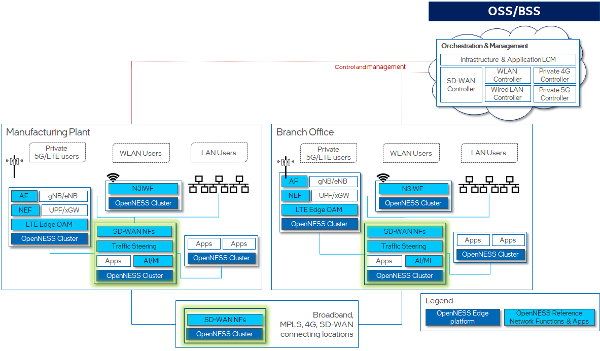
The figure below shows an example of an Smart Edge Open based SD-WAN. In this figure, there are two edge nodes, “Manufacturing Plant” and “Branch Office”. In each node are multiple Smart Edge Open-based clusters, each running the Smart Edge Open edge platform, but supporting different collections of network functions, such as Private 5G (e.g., the AF, NEF, gNB, UPF functions), SD-WAN network functions, or user applications.
In this figure, the SD-WAN implementation is depicted in “SD-WAN NFs” boxes appearing in a number of Smart Edge Open clusters, and an “SD-WAN Controller” appearing in the Orchestration and Management function. Other functions seen in the figure are Smart Edge Open building blocks that the SD-WAN implementation uses to carry out its function.
The next section describes the SD-WAN implementation.
SD-WAN Implementation
The Intel® Smart Edge Open uCPE Experience Kit is based on OpenWrt, an embedded version of Linux designed for use in routers and other communication devices. OpenWrt is highly customizable, allowing it to be deployed with a small footprint, and has a fully-writable filesystem. More details about OpenWRT can be found here.
The OpenWrt project provides a number of kernel images. The “x86-generic rootfs” image is used in the SD-WAN implementation
The OpenWrt project contains a number of packages of use in implementing SD-WAN functional elements, which are written as OpenWrt applications. These include:
-
mwan3 (for Multiple WAN link support) mwan
-
firewall3 (for firewall, SNAT, DNAT) fw3
-
strongswan (for IPsec) strongswan
These packages support the following functionality:
-
IPsec tunnels across K8s clusters;
-
Support of multiple types of K8s clusters:
-
K8s clusters having static public IP address,
-
K8s clusters having dynamic public IP address with static FQDN, and
-
K8s clusters with no public IP;
-
-
Stateful inspection firewall (for inbound and outbound connections);
-
Source NAT and Destination NAT for K8s clusters whose POD and ClusterIP subnets are overlapping;
-
Multiple WAN links.
The SD-WAN implementation uses the following three primary components:
-
SD-WAN Cloud-Native Network Function (CNF) based on OpenWrt packages;
-
Custom Resource Definition (CRD) Controller;
-
Custom Resource Definitions (CRD).
The CNF contains the OpenWrt services that perform SD-WANM operations. The CRD Controller and CRDs allow Custom Resources (i.e., extensions to Kubernetes APIs) to be created. Together these components allow information to be sent and received, and commands performed, from the Kubernetes Controller to the SD-WAN.
This behavior is described in the following subsections.
SD-WAN CNF
The SD-WAN CNF is deployed as a pod with external network connections. The CNF runs the mwan, mwan3, and strongswan applications, as described in the previous section. The configuration parameters for the CNF include:
-
LAN interface configuration – to create and connect virtual, local networks within the edge cluster (local branch) to the CNF.
-
WAN interface configuration – to initialize interfaces that connect the CNF and connected LANs to the external Internet - WAN and to initialize the traffic rules (e.g., policy, rules) for the interfaces. The external WAN is also referred to in this document as a provider network.
SD-WAN traffic rules and WAN interfaces are configured at runtime via a RESTful API. The CNF implements the Luci CGI plugin to provide this API. The API calls are initiated and passed to the CNF by a CRD Controller described in the next paragraph. The API provides the capability to list available SD-WAN services (e.g., mwan3, firewall, and ipsec), get service status, and execute service operations for adding, viewing, and deleting settings for these services.
SD-WAN CRD Controller
The CRD Controller (also referred to in the implementation as a Config Agent), interacts with the SD-WAN CNF via RESTful API calls. It monitors CRs applied through K8s APIs and translates them into API calls that carry the CNF configuration to the CNF instance.
the CRD Controller includes several functions:
-
Mwan3conf Controller, to monitor the Mwan3Conf CR;
-
FirewallConf Controller, to monitor the FirewallConf CR;
-
IPSec Controller, to monitor the IPsec CRs.
Custom Resources (CRs)
As explained above, the behavior of the SD-WAN is governed by rules established in the CNF services. In order to set these rules externally, CRs are defined to allow rules to be transmitted from the Kubernetes API. The CRs are created from the CRDs that are part of the SD-WAN implementation.
The types of rules supported by the CRs are:
-
Mwan3 class, with 2 subclasses, mwan3_policy and mwan3_rule.
-
The firewall class has 5 kinds of rules: firewall_zone, firewall_snat, firewall_dnat, firewall_forwarding, firewall_rule.
-
IPsec class.
The rules are defined by the OpenWrt services, and can be found in the OpenWrt documentation, e.g., here.
Each kind of SD-WAN rule corresponds to a CRD, which are used to instantiate the CRs.
In a Kubernetes namespace, with more than one CNF deployment and many SD-WAN rule CRDs, labels are used to correlate a CNF with SD-WAN rule CRDs.
CNF Configuration via OpenWRT Packages
As explained earlier, the SD-WAN CNF contains a collection of services, implemented by OpenWRT packages. In this section, the services are described in greater detail.
Multi WAN (Mwan3)
The OpenWRT mwan3 service provides capabilities for multiple WAN management: WAN interfaces management, outbound traffic rules, traffic load balancing etc. The service allows an edge to connect to WANs of different providers and and to specify different rules for the links.
According to the OpenWRT website, mwan3 provides the following functionality and capabilities:
-
Provides outbound WAN traffic load balancing or fail-over with multiple WAN interfaces based on a numeric weight assignment.
-
Monitors each WAN connection using repeated ping tests and can automatically route outbound traffic to another WAN interface if a current WAN interface loses connectivity.
-
Creates outbound traffic rules to customize which outbound connections should use which WAN interface (i.e., policy-based routing). This can be customized based on source IP, destination IP, source port(s), destination port(s), type of IP protocol, and other parameters.
-
Supports physical and/or logical WAN interfaces.
-
Uses the firewall mask (default 0x3F00) to mark outgoing traffic, which can be configured in the /etc/config/mwan3 globals section, and can be mixed with other packages that use the firewall masking feature. This value is also used to set the number of supported interfaces.
Mwan3 is useful for routers with multiple internet connections, where users have control over the traffic that flows to a specific WAN interface. It can handle multiple levels of primary and backup interfaces, where different sources can have different primary or backup WANs. Mwan3 uses Netfilter mark mask, in order to be compatible with other packages (e.g., OpenVPN, PPTP VPN, QoS-script, Tunnels), so that traffic can also be routed based on the default routing table.
Mwan3 is triggered by a hotplug event when an interface comes up, causing it to create a new custom routing table and iptables rules for the interface. It then sets up iptables rules and uses iptables MARK to mark certain traffic. Based on these rules, the kernel determines which routing table to use. Once all the routes and rules are initially set up, mwan3 exits. Thereafter, the kernel takes care of all the routing decisions. A monitoring script, mwan3track, runs in the background, running ping to verify that each WAN interface is up. If an interface goes down, mwan3track issues a hotplug event to cause mwan3 to adjust routing tables in response to the interface failure, and to delete all the rules and routes to that interface.
Another component, mwan3rtmon, keeps the main routing table in sync with the interface routing tables by monitoring routing table changes.
Mwan3 is configured when it is started, according to a configuration with the following paragraphs:
-
Global: common configuration spec, used to configure routable loopback address (for OpenWRT 18.06).
-
Interface: defines how each WAN interface is tested for up/down status.
-
Member: represents an interface with a metric and a weight value.
-
Policy: defines how traffic is routed through the different WAN interface(s).
-
Rule: describes what traffic to match and what policy to assign for that traffic.
A SD-WAN CNF will be created with Global and Interface sections initialized based on the interfaces allocated to it. Once the CNF starts, the SD-WAN MWAN3 CNF API can be used to get/create/update/delete an mwan3 rule and policy, on a per member basis.
Firewall (fw3)
OpenWrt uses the firewall3 (fw3) netfilter/iptable rule builder application. It runs in user space to parse a configuration file into a set of iptables rules, sending each of the rules to the kernel netfilter modules. The fw3 application is used by OpenWRT to “safely” construct a rule set, while hiding much of the details. The fw3 configuration automatically provides the router with a base set of rules and an understandable configuration file for additional rules.
Similarly to the iptables application, fw3 is based on libiptc library that is used to communicate with the netfilter kernel modules. Both fw3 and iptables applications follow the same steps to apply rules on Netfilter:
-
Establish a socket and read the netfilter table into the application.
-
Modify the chains, rules, etc. in the table (all parsing and error checking is done in user-space by libiptc).
-
Replace the netfilter table in the kernel
fw3 is typically managed by invoking the shell script /etc/init.d/firewall, which accepts the following set of arguments (start, stop, restart, reload, flush). Behind the scenes, /etc/init.d/firewall then calls fw3, passing the supplied argument to the binary.
OpenWRT firewall is configured when it is started, via a configuration file with the following paragraphs:
-
Default: declares global firewall settings that do not belong to specific zones.
-
Include: used to enable customized firewall scripts.
-
Zone: groups one or more interfaces and serves as a source or destination for forwardings, rules, and redirects.
-
Forwarding: control the traffic between zones.
-
Redirect: defines port forwarding (NAT) rules
-
Rule: defines basic accept, drop, or reject rules to allow or restrict access to specific ports or hosts.
The SD-WAN firewall API provides support to get/create/update/delete Firewall Zone, Redirect, Rule, and Forwardings.
IPSec
The SD-WAN leverages IPSec functionality to setup secure tunnels for Edge-to-WAN and Edge-WAN-Edge (i.e., to interconnect two edges) communication. The SD-WAN uses the OpenWrt StrongSwan implementation of IPSec. IPsec rules are integrated with the OpenWRT firewall, which enables custom firewall rules. StrongSwan uses the default firewall mechanism to update the firewall rules and injects all the additionally required settings, according to the IPsec configuration stored in /etc/config/ipsec .
The SD-WAN configures the IPSec site-to-site tunnels to connect edge networks through a hub located in the external network. The hub is a server that acts as a proxy between pairs of edges. The hub also runs SD-WAN CRD Controller and CNF configured such that it knows how to access SD-WAN CNFs deployed on both edges. In that case, to create the IPsec tunnel, the WAN interface on the edge is treated as one side of the tunnel, and the connected WAN interface on the hub is configured as the “responder”. Both edges are configured as “initiator”.
SD-WAN CNF Packet Flow
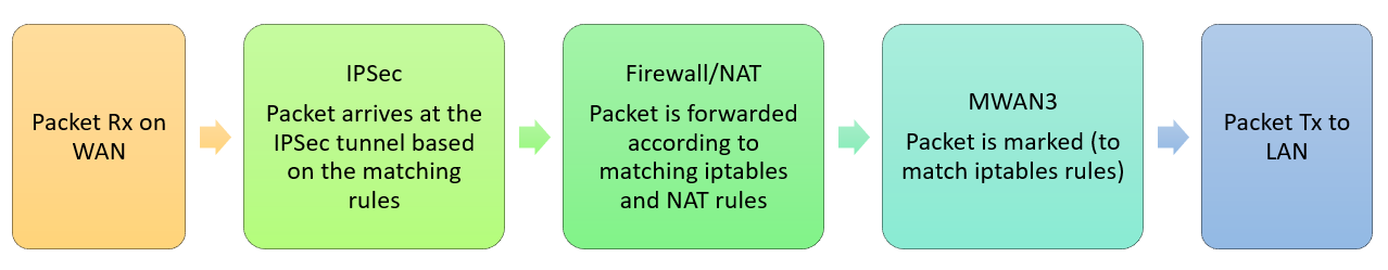
Packets that arrives at the edge come through a WAN link that connects the edge to an external provoder network. This WAN interface should be already configured with traffic rules. If there is an IPSec tunnel created on the WAN interface, the packet enters the IPSec tunnel and is forwarded according to IPSec and Firewall/NAT rules. The packet eventually leaves the CNF via a LAN link connecting the OVN network on the edge.
The following figure shows the typical packet flow through the SD-WAN CNF for Rx (WAN to LAN) when a packet sent from external network enters the edge cluster:
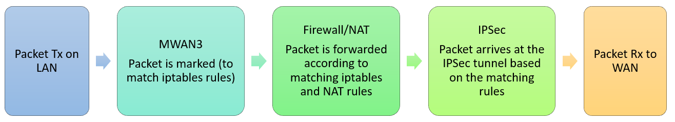
Packets that attempt to leave the edge come into the CNF through a LAN link attached to the OVN network on the edge cluster. This packet is then marked by the mwan3 application. This mark is used by the firewall to apply rules on the packet, and steer it to the proper WAN link used by the IPSec tunnel connecting the CNF to the WAN. The packet enters the IPSec tunnel and leaves the edge through the WAN interface.
The following figure shows the typical packet flow through the SD-WAN CNF for Tx (LAN to WAN), when a packet leaves from the edge cluster to the external network:
Intel® Smart Edge Open Integration
The previous sections of this document describe the operation of an SD-WAN implemention built from OpenWrt and its various packages. We now turn to the subject of how the SD-WAN is integrated with Intel® Smart Edge Open.
Goals
Intel® Smart Edge Open leverages the SD-WAN project to offer SD-WAN service within an on-premise edge, to enable secure and optimized inter-edge data transfer. This functionality is sought by global corporations with branch offices distributed across many geographical locations, as it creates an optimized WAN between edge locations implemented on top of a public network.
At least one SD-WAN CNF is expected to run on each Smart Edge Open cluster (as shown in a previous figure), and act as a proxy for edge applications traffic entering and exiting the cluster. The primary task for the CNF is to provide software-defined routes connecting the edge LANs with the (public network) WAN.
Currently, the Smart Edge Open SD-WAN is intended only for single node clusters, accommodating only one instance of a CNF and a CRD Controller.
Networking Implementation
Intel® Smart Edge Open deployment featuring SD-WAN implements networking within the cluster with three CNIs:
- calico CNI, that acts as the primary CNI.
- ovn4nfv k8s plugin CNI that acts as the secondary CNI.
- Multus CNI, that allows for attaching multiple network interfaces to pods, required by the CNF pod. Without Multus, Kubernetes pods could support only one network interface.
The Calico CNI is used to configure the default network overlay for the Smart Edge Open cluster. It provides the commuication between the pods of the cluster and acts as the management interface. Calico is considered a lighter solution than Kube-OVN, which currently is the preferable CNI plugin for the primary network in Smart Edge Open clusters.
The ovn4nfv-k8s-plugin is a CNI plugin based on OVN and OpenVSwitch (OVS). It works with the Multus CNI to add multiple interfaces to the pod. If Multus is used, the net1 interface is by convention the OVN default interface that connects to Multus. The other interfaces are added by ovn4nfv-k8s-plugin according to the pod annotation. With ovn4nfv-k8s-plugin, virtual networks can be created at runtime. The CNI plugin also utilises physical interfaces to connect a pod to an external network (provider network). This is particularly important for the SD-WAN CNF. ovn4nfv also enables Service Function Chaining (SFC).
In order for the SD-WAN CNF to act as a proxy between the virtual LANs in the cluster and the WAN, it needs to have two types of network interfaces configured:
- A virtual LAN network on one of the CNF’s virtual interfaces. This connects application pods belonging to the same OVN network in the cluster. The ovn4nfv plugin allows for simplified creation of a virtual OVN network based on the provided configuration. The network is then attached on one of the CNF’s interfaces.
- A provider network, to connect the CNF pod to an external network (WAN). The provider network is attached to the physical network infrastructure via layer-2 (i.e., via bridging/switching).
Converged Edge Reference Architectures (Intel® Smart Edge Open Experience Kits)
Intel® Smart Edge Open Experience Kit is a business program that creates and maintains validated reference architectures of edge networks, including both hardware and software elements. The reference architectures are used by ISVs, system integrators, and others to accelerate the development of production edge computing systems.
The Intel® Smart Edge Open project has created an Intel® Smart Edge Open Experience Kit reference architecture for SD-WAN edge and SD-WAN hub. They are used, with Intel® Smart Edge Open, to create a uCPE platform for an SD-WAN CNF on edge and hub accordingly. Even though there is only one implementation of CNF, it can be used for two different purposes, as described below.
SD-WAN Edge Reference Architecture
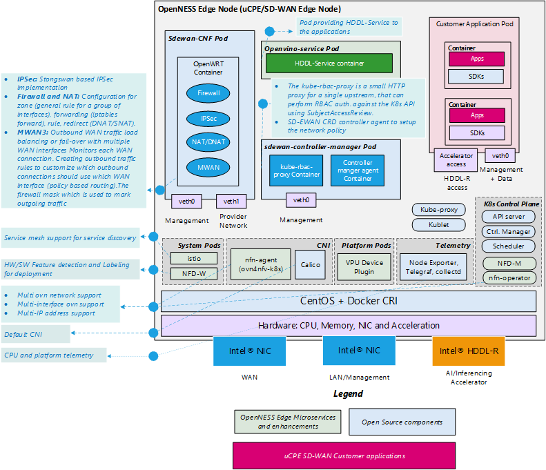
The SD-WAN Edge Smart Edge Open Experience Kit reference implementation is used to deploy SD-WAN CNF on a single-node edge cluster that will also accomodate enterprize edge applications. The major goal of SD-WAN Edge is to support the creation of a Kubernetes-based platform that boosts the performance of deployed edge applications and reduces resource usage by the Kubernetes system. To accomplish this, the underlying platform must be optimized and made ready to use IA accelerators. Smart Edge Open provides support for the deployment of OpenVINO™ applications and workloads acceleration with the Intel® Movidius™ VPU HDDL-R add-in card. SD-WAN Edge also enables the Node Feature Discovery (NFD) building block on the cluster to provide awareness of the nodes’ features to edge applications. Finally, SD-WAN Edge implements Istio Service Mesh (SM) in the default namespace to connect the edge applications. SM acts as a middleware between edge applications/services and the Smart Edge Open platform, and provides abstractions for traffic management, observability, and security of the building blocks in the platform. Istio is a cloud-native service mesh that provides capabilities such as Traffic Management, Security, and Observability uniformly across a network of services. Smart Edge Open integrates with Istio to reduce the complexity of large scale edge applications, services, and network functions. More information on SM in Smart Edge Open can be found on the Smart Edge Open website.
To minimalize resource consumption by the cluster, SD-WAN Edge disables services such as EAA, Edge DNS, and Kafka. Telemetry service stays active for all the Kubernetes deployments.
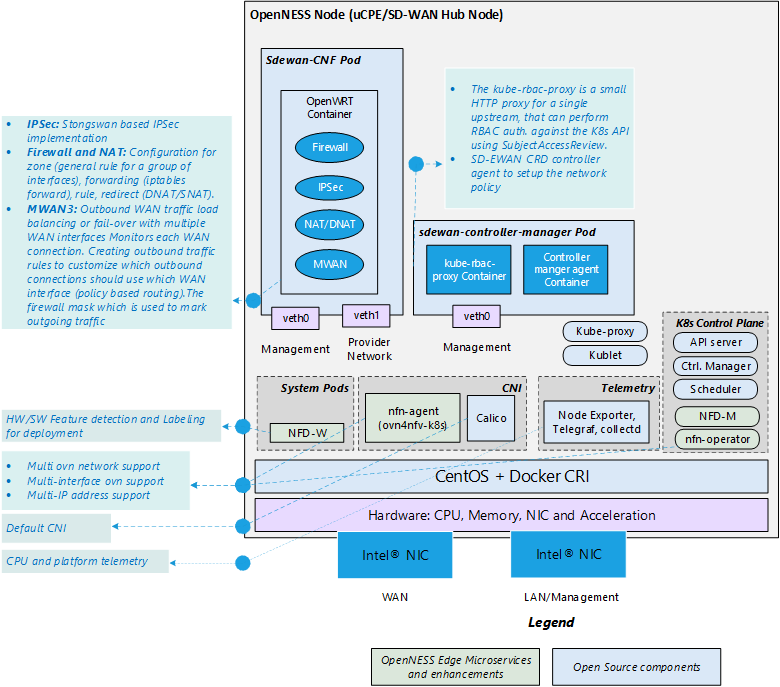
The following figure shows the system architecture of the SD-WAN Edge Reference Architecture.
SD-WAN Hub Reference Architecture
The SD-WAN Hub reference architecture prepares an Smart Edge Open platform for a single-node cluster that functions primarily as an SD-WAN hub. That cluster will also deploy a SD-WAN CRD Controller and a CNF, but no other corporate applications are expected to run on it. That is why the node does not enable support for an HDDL card or for Network Feature Discovery and Service Mesh.
The Hub is another Smart Edge Open single-node cluster that acts as a proxy between different edge clusters. The Hub is essential to connect edges through a WAN when applications within the edge clusters have no public IP addresses, which requires additional routing rules to provide access. These rules can be configured globally on a device acting as a hub for the edge locations.
The Hub node has two expected use-cases:
-
If the edge application wants to access the internet, or an external application wants to access service running in the edge node, the Hub node can act as a gateway with a security policy in force.
-
For communication between a pair of edge nodes located at different locations (and in different clusters), if both edge nodes have public IP addresses, then an IP Tunnel can be configured directly between the edge clusters, otherwise the Hub node is required to act as a proxy to enable the communication.
The following figure shows the system architecture of the SD-WAN Hub Reference Architecture.
Deployment
E2E Scenarios
Three end-to-end scenarios have been validated to verify deployment of an SD-WAN on Smart Edge Open. The three scenarios are described in the following sections of this document.
Hardware Specification
The following table describes the hardware requirements of the scenarios.
| Hardware | UE | Edge & Hub | |
|---|---|---|---|
| CPU | Model name: | Intel(R) Xeon(R) | Intel(R) Xeon(R) D-2145NT |
| CPU E5-2658 v3 @ 2.20GHz | CPU @ 1.90GHz | ||
| CPU MHz: | 1478.527 | CPU MHz: 1900.000 | |
| L1d cache: | 32K | 32K | |
| L1i cache: | 32K | 32K | |
| L2 cache: | 256K | 1024K | |
| L3 cache: | 30720K | 1126K | |
| NUMA node0 CPU(s): | 0-11 | 0-15 | |
| NUMA node1 CPU(s): | 12-23 | ||
| NIC | Ethernet controller: | Intel Corporation | Intel Corporation |
| 82599ES 10-Gigabit | Ethernet Connection | ||
| SFI/SFP+ Network Connection | X722 for 10GbE SFP+ | ||
| (rev 01) | Subsystem: Advantech Co. Ltd | ||
| Subsystem: Intel Corporation | Device 301d | ||
| Ethernet Server Adapter X520-2 | |||
| HDDL |
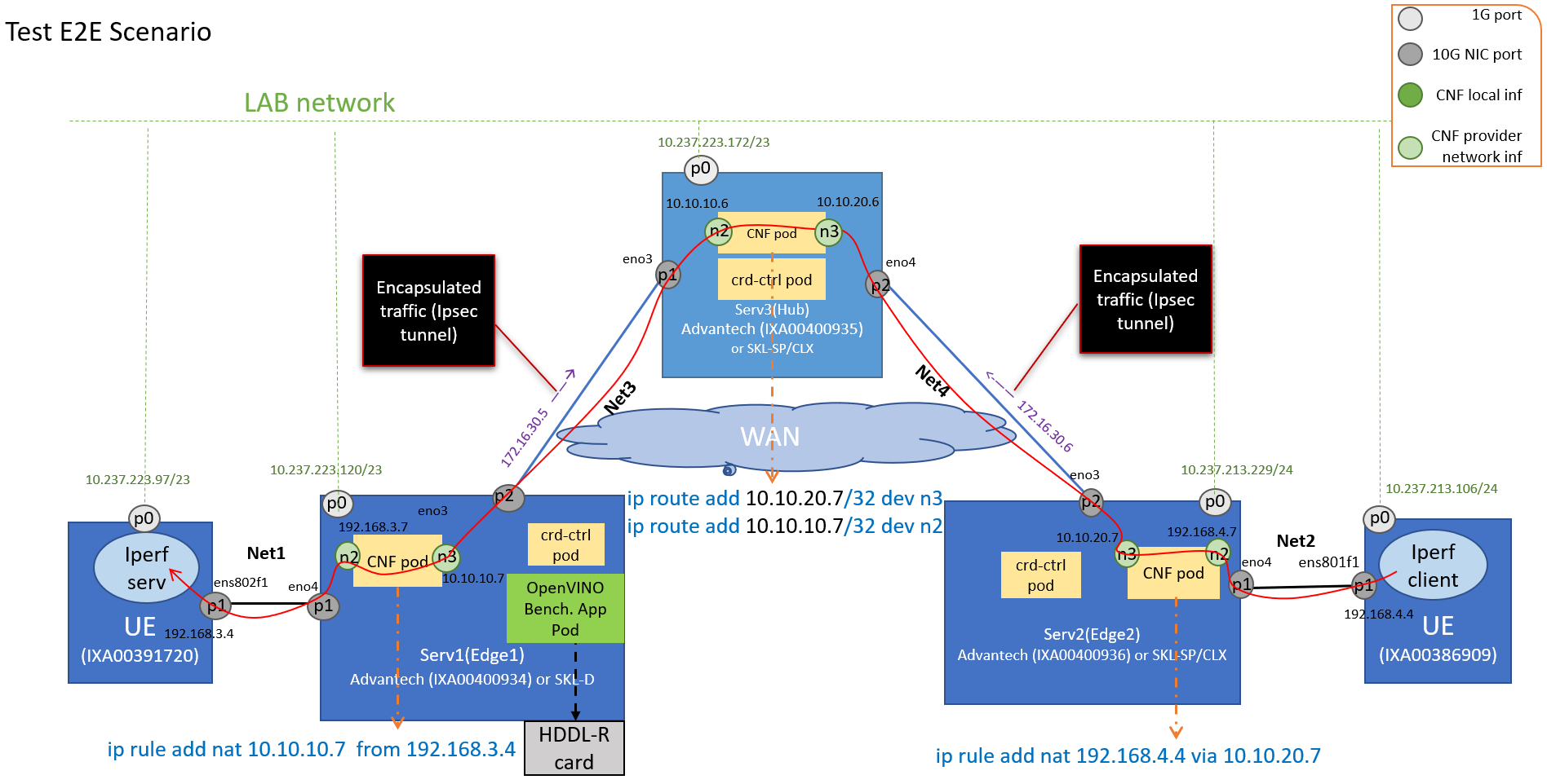
Scenario 1
In this scenario, two UEs are connected to two separate edge nodes, which are connected to one common hub. The scenario demonstrates basic connectivity accross the edge clusters via the SD-WAN. The traffic flow is initiated on one UE and received on the other UE.
For this scenario, Smart Edge Open is deployed on both edges and on the hub. On each edge and hub, an SD-WAN CRD Controller and a CNF are set up. Then CRs are used to configre the CNFs and to set up IPsec tunnels between each edge and the hub, and to configure rules on the WAN interfaces connecting edges with the hub. Each CNF is connected to two provider networks. The CNFs on Edge 1 and Edge 2 use provider network n2 to connect to UEs outside the Edge, and the provider network n3 to connect the hub in another edge location. Currently, the UE connects to the CNF directly without the switch. In the following figure, UE1 is in the same network(NET1) as Edge1 port. It is considered a private network.
This scenario verifies that sample traffic can be sent from the UE connected to Edge2 to another UE connected to Edge1 over secure WAN links connecting the edges to a hub. To demonstrate this connectivity, traffic from the Iperf-client application running on the Edge2 UE is sent toward the Edge1 UE running the Iperf server application.
The Edge1 node also deploys an OpenVINO app, and, in this way, this scenario also demonstrates Scenario 3 described below.
A more detailed description of this E2E test is provided under the link in the Smart Edge Open documentation for this SD-WAN scenario.
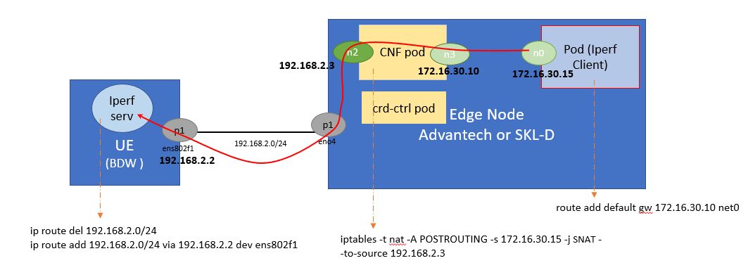
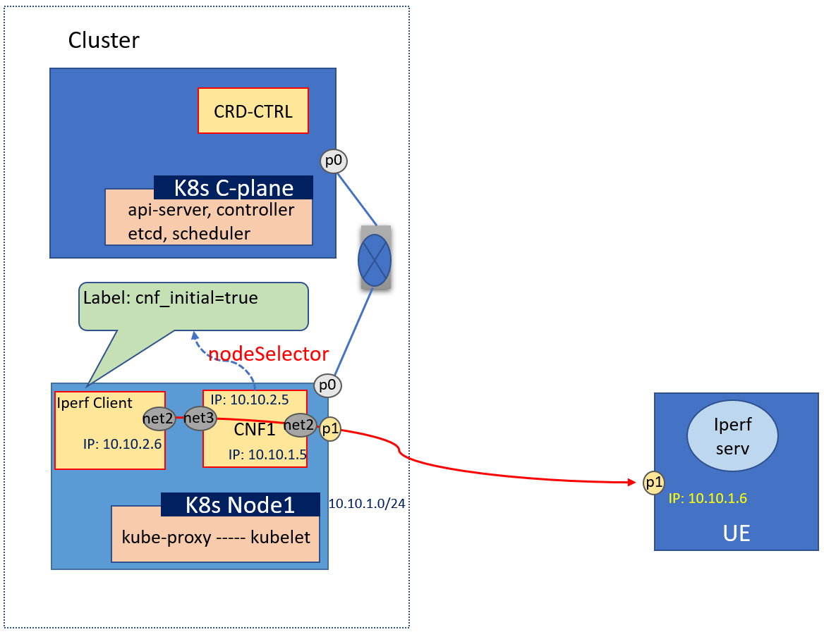
Scenario 2
This scenario demonstrates an simple Smart Edge Open SD-WAN with a single node cluster, that deploys an SD-WAN CNF and an application pod running an Iperf client. The scenario is depicted in the following figure.
The CNF pod and Iperf-client pod are attached to one virtual OVN network, using the n3 and n0 interfaces respectively. The CNF has configured a provider network on interface n2, that is attached to a physical interface on the Edge node to work as a bridge, to connect the external network. This scenario demonstrates that, after configuration of the CNF, the traffic sent from the application pod uses the SD-WAN CNF as a proxy, and arrives at the User Equipment (UE) in the external network. The E2E traffic from the Iperf3 client application on the application pod (which is deployed on the Edge node) travels to the external UE via a 10G NIC port. The UE runs the Iperf3 server application. The Smart Edge Open cluster, consisting of the Edge Node server, is deployed on the SD-WAN Edge. The Iperf client traffic is expected to pass through the SD-WAN CNF and the attached provider network interface to reach the Iperf server that is listening on the UE.
A more detailed description of the scenarion can be found in this SD-WAN scenario documentation
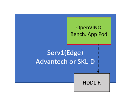
Scenario 3
This scenario a sample OpenVINO benchmark application deployed on an Smart Edge Open edge platform equipped with an HDDL accelerator card. It reflects the use case in which a high performance OpenVINO application is executed on an Smart Edge Open single node cluster, deployed with an SD-WAN Edge. The SD-WAN Edge enables an HDDL plugin to provide the Smart Edge Open platform with support for workload acceleration via the HDDL card. More information on the OpenVINO sample application is provided under the following links:
A more detailed description of this scenario is available in Smart Edge Open documentation
EWO Configuration
There are five types configuration for EWO. With these configurations, it is easy to deploy the above scenarios automatically.
NodeSelector For CNF
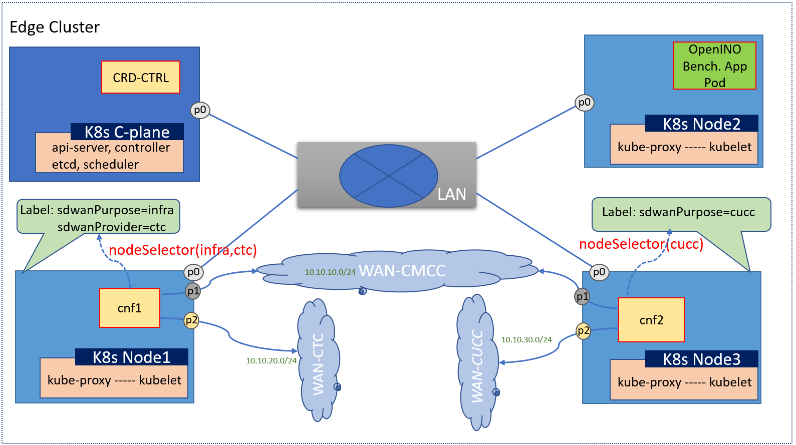 This configuration is used to choose a node to install CNFs.
For this example, we want to setup a cnf on node1 and another cnf on node3, the configurations snippet as below:
This configuration is used to choose a node to install CNFs.
For this example, we want to setup a cnf on node1 and another cnf on node3, the configurations snippet as below:
inventory/default/host_vars/node1/30-ewo.yml
sdwan_labels: '{"sdwanPurpose": "infra", "sdwanProvider": "operator_A"}'
and
inventory/default/host_vars/node3/30-ewo.yml
sdwan_labels: '{"sdwanProvider": "operator_B"}'
NOTE An alternative configuration: You can also define the sdwan_labels in inventory.yml. If only deploy cnfs on node3, the snippet configuration as follow:
edgenode_group:
  hosts:
    node01:
      ansible_host: 172.16.0.1
      ansible_user: openness
    node02:
      ansible_host: 172.16.0.2
      ansible_user: openness
    node03:
      ansible_host: 172.16.0.3
      ansible_user: openness
      sdwan_labels: {"sdwanProvider": "operator_A"}
Network and CNF Interface
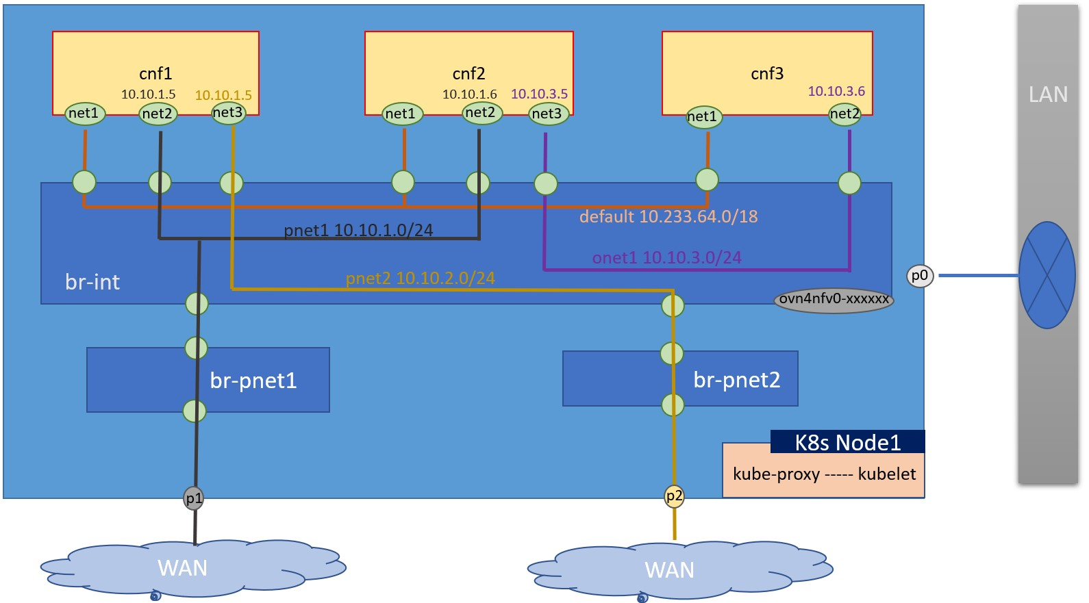 This configuration is used to setup ovn WAN or cluster networks and attach the cnfs to the network.
For this example, we want to setup 4 networks with different color lines (black/yellow/orage/purple). The balck and yellow are 2 different WAN networks. The configurations snippet as below:
This configuration is used to setup ovn WAN or cluster networks and attach the cnfs to the network.
For this example, we want to setup 4 networks with different color lines (black/yellow/orage/purple). The balck and yellow are 2 different WAN networks. The configurations snippet as below:
in inventory/default/host_vars/node1/30-ewo.yml, flavors/sdewan-edge/all.yml(edge cluster as example) if only set cnfs on one node.
pnet1_name: pnetwork1
pnet2_name: pnetwork2
onet1_name: onetwork1

# A list of network definitions. It can be provider network or ovn4nfv network.
# ovn4nfv should be configured as the secondary CNI for cluster network in this
# situation. And the user can use the configuration to customize networks
# according to needs.
networks:
  - networkname: ""
    subnname: "pnet1_subnet"
    subnet: 10.10.1.0/24
    gateway: 10.10.1.1
    excludeIps: 10.10.1.2..10.10.1.9
    providerNetType: "DIRECT"
    providerInterfaceName: "p1"
  - networkname: ""
    subnname: "pnet2_subnet"
    subnet: 10.10.2.0/24
    gateway: 10.10.2.1
    excludeIps: 10.10.2.2..10.10.2.9
    providerNetType: "DIRECT"
    providerInterfaceName: "p2"
  - networkname: ""
    subnname: "onet1_subnet"
    subnet: 10.10.3.0/24
    gateway: 10.10.3.1
    excludeIps: 10.10.3.2..10.10.3.9
    providerNetType: "NONE"

# CNF pod info
cnf_config:
 - name: "cnf1"
   interfaces:
     - ipAddress: "10.10.1.5"
       name: "net2"
       belongto: ""
     - ipAddress: "10.10.1.6"
       name: "net3"
       belongto: ""
     - ipAddress: "10.10.3.5"
       name: "net4"
       belongto: ""
Tunnel
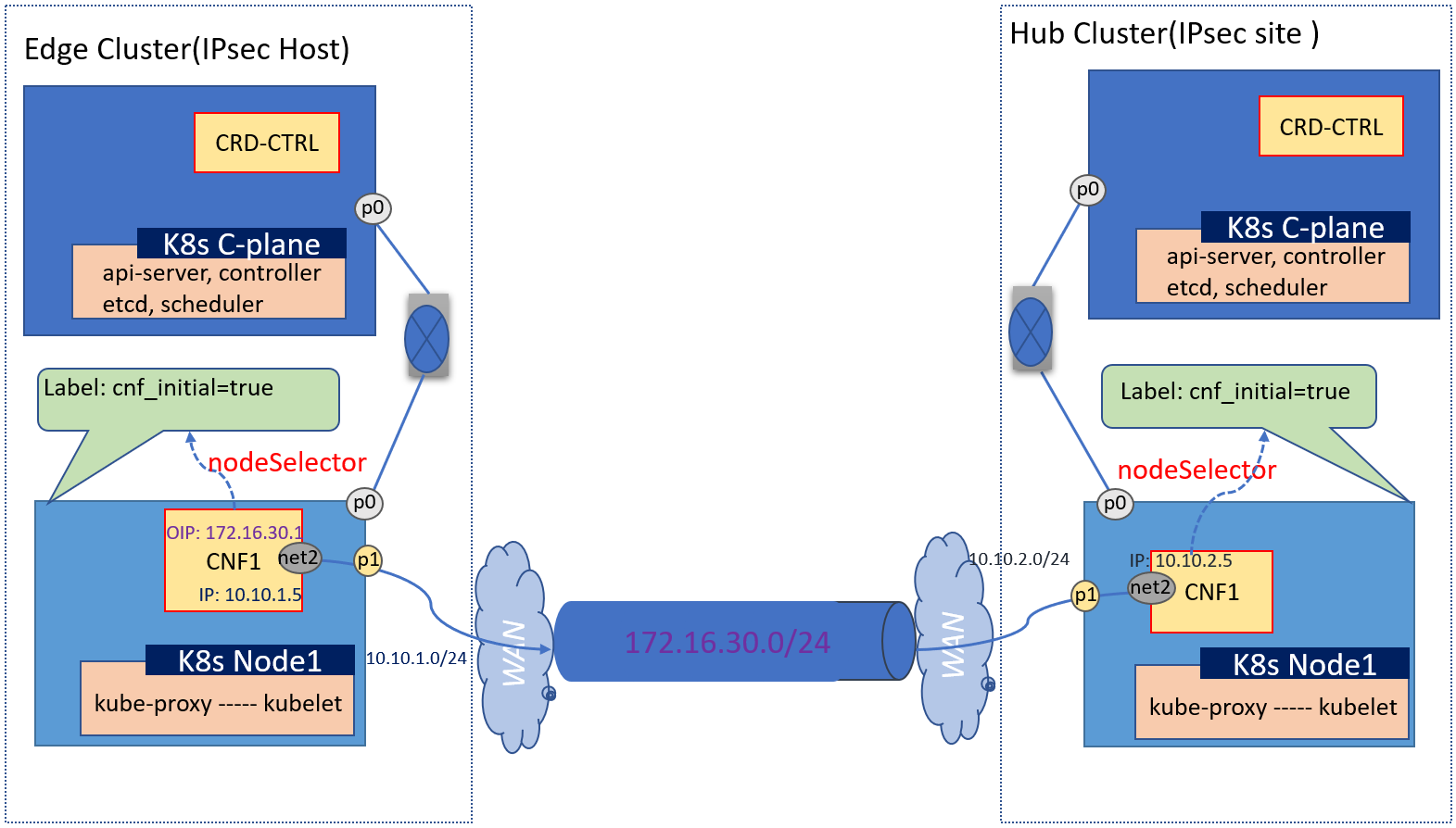 This configuration is used to setup an IPsec tunnel between 2 clusters.
The configurations snippet for the edge cluster(left) as below:
This configuration is used to setup an IPsec tunnel between 2 clusters.
The configurations snippet for the edge cluster(left) as below:
in inventory/default/host_vars/node1/30-ewo.yml, or flavors/sdewan-edge/all.yml(edge cluster as example) if only set cnfs on one node.
pnet1_name: pnetwork1
# A list of network definitions. It can be provider network or ovn4nfv network.
# ovn4nfv should be configured as the secondary CNI for cluster network in this
# situation. And the user can use the configuration to customize networks
# according to needs.
networks:
  - networkname: ""
    subnname: "pnet1_subnet"
    subnet: 10.10.1.0/24
    gateway: 10.10.1.1
    excludeIps: 10.10.1.2..10.10.1.9
    providerNetType: "DIRECT"
    providerInterfaceName: "p1"

# overlay network
O_TUNNEL_NET: 172.16.30.0/24

# CNF pod info
cnf_config:
 - name: "cnf1"
   interfaces:
     - ipAddress: "10.10.1.5"
       name: "net2"
       belongto: ""
   rules:
     - name: tunnel1
       type: tunnelhost
       local_identifier: 10.10.1.5
       remote: 10.10.2.5
       remote_subnet: ",10.10.2.5/32"
       remote_sourceip:
       local_subnet:
The configurations snippet for the hub cluster(right) as below:
in inventory/default/host_vars/node1/30-ewo.yml, or flavors/sdewan-edge/all.yml(edge cluster as example) if only set cnfs on one node.
pnet1_name: pnetwork1

# A list of network definitions. It can be provider network or ovn4nfv network.
# ovn4nfv should be configured as the secondary CNI for cluster network in this
# situation. And the user can use the configuration to customize networks
# according to needs.
networks:
  - networkname: ""
    subnname: "pnet2_subnet"
    subnet: 10.10.2.0/24
    gateway: 10.10.2.1
    excludeIps: 10.10.2.2..10.10.2.9
    providerNetType: "DIRECT"
    providerInterfaceName: "p1"

# overlay network
O_TUNNEL_NET: 172.16.30.0/24

# CNF pod info
cnf_config:
 - name: "cnf1"
   interfaces:
     - ipAddress: "10.10.2.5"
       name: "net2"
       belongto: ""
   rules:
     - name: tunnel1
       type: tunnelsite
       local_identifier:
       local_sourceip:
       remote_sourceip: ""
       local_subnet: ",10.10.2.5/32"
SNAT
 This configuration is used to setup an SNAT when an app pod in clusters want to access the external network, for example it wants to access the service on internet.
The configurations snippet as below:
This configuration is used to setup an SNAT when an app pod in clusters want to access the external network, for example it wants to access the service on internet.
The configurations snippet as below:
in inventory/default/host_vars/node1/30-ewo.yml, or flavors/sdewan-edge/all.yml(edge cluster as example) if only set cnfs on one node.
pnet1_name: pnetwork1
pnet2_name: pnetwork2

# A list of network definitions. It can be provider network or ovn4nfv network.
# ovn4nfv should be configured as the secondary CNI for cluster network in this
# situation. And the user can use the configuration to customize networks
# according to needs.
networks:
  - networkname: ""
    subnname: "pnet1_subnet"
    subnet: 10.10.1.0/24
    gateway: 10.10.1.1
    excludeIps: 10.10.1.2..10.10.1.9
    providerNetType: "DIRECT"
    providerInterfaceName: "p1"
  - networkname: ""
    subnname: "pnet2_subnet"
    subnet: 10.10.2.0/24
    gateway: 10.10.2.1
    excludeIps: 10.10.2.2..10.10.2.9
    providerNetType: "DIRECT"
    providerInterfaceName: "p2"

# CNF pod info
cnf_config:
 - name: "cnf1"
   interfaces:
     - ipAddress: "10.10.1.5"
       name: "net2"
       belongto: ""
     - ipAddress: "10.10.1.6"
       name: "net3"
       belongto: ""
     - name: snat1
       type: snat
       network: 10.10.1.0/24
       private: 10.10.2.6
       via: 10.10.1.5
       provider: ""
DNAT
This configuration is used to setup an DNAT when outer traffic comes into the cluster, for example, when an app pod exposes a service to internet.
The configurations snippet as below:
in inventory/default/host_vars/node1/30-ewo.yml, or flavors/sdewan-edge/all.yml(edge cluster as example) if only set cnfs on one node.
pnet1_name: pnetwork1
pnet2_name: pnetwork2

# A list of network definitions. It can be provider network or ovn4nfv network.
# ovn4nfv should be configured as the secondary CNI for cluster network in this
# situation. And the user can use the configuration to customize networks
# according to needs.
networks:
  - networkname: ""
    subnname: "pnet1_subnet"
    subnet: 10.10.1.0/24
    gateway: 10.10.1.1
    excludeIps: 10.10.1.2..10.10.1.9
    providerNetType: "DIRECT"
    providerInterfaceName: "p1"
  - networkname: ""
    subnname: "pnet2_subnet"
    subnet: 10.10.2.0/24
    gateway: 10.10.2.1
    excludeIps: 10.10.2.2..10.10.2.9
    providerNetType: "DIRECT"
    providerInterfaceName: "p2"

# CNF pod info
cnf_config:
 - name: "cnf1"
   interfaces:
     - ipAddress: "10.10.1.5"
       name: "net2"
       belongto: ""
     - ipAddress: "10.10.1.6"
       name: "net3"
       belongto: ""
     - name: dnat1
       type: dnat
       from: 10.10.1.6
       ingress: 10.10.2.5
       network: 10.10.2.0/24
       provider: ""
Resource Consumption
Methodology
The resource consumption of CPU and memory was measured.
To measure the CPU and memory resource consumption of the Kubernetes cluster, the “kubctl top pod -A” command was invoked both on the Edge node and the Edge Hub.
The resource consumption was measured twice:
-
With no IPerf traffic;
-
With IPerf traffic from Edge2-UE to Edge1-UE.
To measure total memory usage, the command “free -h” was used.
Results
| Option | Resource | Edge | Hub |
|---|---|---|---|
| Without traffic | CPU | 339m (0.339 CPU) | 327m (0.327 CPU) |
| RAM | 2050Mi (2.05G) | 2162Mi (2.162G) | |
| Total mem used | 3.1G | 3.1G | |
| With Iperf traffic | CPU | 382m(0.382 CPU) | 404m(0.404 CPU) |
| RAM | 2071Mi(2.071G) | 2186Mi(2.186G) | |
| Total mem used | 3.1G | 3.1 |
References
- ICN SDEWAN documentation
- ovn4nfv k8s plugin documentation
- Service Function Chaining (SFC) Setup
- Utilizing a Service Mesh for Edge Services in Smart Edge Open
- Using Intel® Movidius™ Myriad™ X High Density Deep Learning (HDDL) solution in Smart Edge Open
- Node Feature Discovery support in Smart Edge Open
- OpenVINO™ Sample Application in Smart Edge Open
Acronyms
| API | Application Programming Interface |
| CERA | Converged Edge Reference Architectures |
| CR | Custom Resource |
| CRD | Custom Resource Definition |
| CNF | Cloud-native Network Function |
| DNAT | Destination Network Address Translation |
| HDDL | High Density Deep Learning |
| IP | Internet Protocol |
| NAT | Network Address Translation |
| NFD | Network Feature Discovery |
| SM | Service Mesh |
| SD-WAN | Software-Defined Wide Area Network |
| SNAT | Source Network Address Translation |
| TCP | Transmission Control Protocol |
| uCPE | Universal Customer Premise Equipment |
Terminology
| Term | Description |
|---|---|
| EWO | <p> Edge WAN Overlay</p> |
| Overlay controller | <p> is a Central Controller provides central control of SDEWAN overlay networks by automatically configuring the SDEWAN CNFs through SDEWAN CRD controller located in edge location clusters and hub clusters</p> |
| EWO Controller | <p>To represent central overlay controller</p> |
| EWO Operator | <p>To represent CRD controller</p> |
| EWO CNF | <p>To represent OpenWRT based CNF. </p> |
| SDEWAN CRD Controller | <p>is implemented as k8s CRD Controller, it manages CRDs (e.g. Firewall related CRDs, Mwan3 related CRDs and IPsec related CRDs etc.) and internally calls SDEWAN Restful API to do CNF configuration. And a remote client (e.g. SDEWAN Central Controller) can manage SDEWAN CNF configuration through creating/updating/deleting SDEWAN CRs. </p> |
| OpenWRT based CNF | <p>The CNF is implemented based on OpenWRT, it enhances OpenWRT Luci web interface with SDEWAN controllers to provide Restful API for network functions configuration and control.</p> |